
It is possible to conceptualize, design, and develop plastic components most efficiently, but there are a number of phases (some of which overlap with one another) that must be completed before this can be accomplished.
Here’s how the part is designed in simple terms.
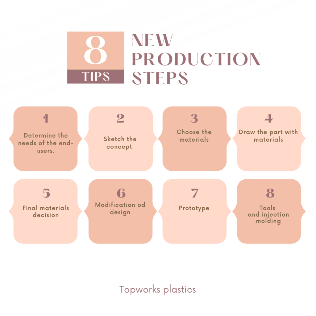
- Determine the needs of the end-users.
- Sketch the concept
- Choose the materials
- Draw the part with materials
- Choose the right material
- Make manufacture simpler
- Prototype
- Tools & Manufacturing
The design process can involve several activities happening simultaneously, but they are discussed separately at different stages.
End-User Requirements Definition
A comprehensive and thorough description of specifications and end-use criteria is provided throughout the entire product development process.
Engineers and designers will create the product based on these requirements, which is the first step in the construction process.
It is not possible to use nonconforming products.
A product should be designed according to its intended end-use, rather than its quality.
When defining solid products, terms such as “strong” or “clear” should be used. Because it is not as straightforward, determining how a product should look and what it should withstand is much more challenging.
However, despite all the possible uses of a product, its use can be difficult to measure when considering the potential misuse of that product. In general, it applies to replacing existing products with new ones (e.g. on a conversion to metal basis), but not when producing completely new products.
It can be difficult to anticipate specifications such as these.
The goal of this stage is typically to create prototypes (or models) to ensure that our understanding of the end-use specifications is complete.
A number of factors must be taken into consideration, including structural loading, environment, size specification, and standard requirements.
There are several factors to consider and define when it comes to loading types, speeds, loading time, and loading frequency. Consider the load while mounting, transporting, storing, and using the product. Plastic components are often designed to ensure that when a product is shipped and stored, it is properly packaged.
In addition to assessing typical loading situations for the part, the manufacturer should consider worst-case scenarios as well. It is crucial to determine which side of the load will be most affected if it fails.
Products that are poorly designed are more likely to fail, while products that haven’t taken misuse into consideration will also fail. It is especially important for product designers to ensure that their designs are reliable when failure will cause serious injury.
Because the properties of plastic materials are extremely sensitive to environmental conditions, it is essential to specify the anticipated environmental conditions for use. In addition to radiation exposure and relative humidity, a chemical environment and a temperature are also required.When assembling and storing items, the environmental conditions to be met (ovens for curing paints, acids, adhesives, etc.) should be carefully examined. A temperature high enough for creep or oxidative degradation is not recommended, and a temperature low enough for creep is also not recommended.
Again, the key to preventing misuse is anticipating it, forming worst-case scenarios, and specifying requirements in advance. Chemicals in the product and any risks of UV exposure must be clearly displayed if the product is intended for outdoor use.
The measurements of plastic parts, as well as their surface finishes, are often critical for practical reasons. Tooling and development costs are significantly affected by differences in measurement tolerance.
In certain applications, plastics are regulated by certain agencies. It is important to know which agency is responsible for a given product.
If you follow this step correctly, conforming to these standards should be easy. A material’s grade (flammability, food quality, etc.) or performance standard can be verified (EMI shielding, for example).
Prototypes or pre-production are often required to assess a product.
The maximum cost of the product and the replacement interval are also specified during the first phase of development.
The product development team’s goal is to develop a product that is attractive and affordable (i.e., the most efficient design). Similarly, other restrictions related to the market, such as size, color, and shape, should also be quantified. As aesthetic values are difficult to quantify, models (prototypes without functional components) are a great way to communicate them.
A business must also consider how long the material will last, as well as the type of material to be used.
Designing products and processes to have the lowest possible costs (i.e., the most efficient projects) is crucial. Market-related constraints such as color and size must always be communicated to consumers.
An early concept sketch
Once the product requirements have been defined, the product development team will collaborate with industrial designers to create early sketches.
These sketches are often 3D renderings, rather than CAD drawings.
Fig. 3.5
Highlight and detail areas of the part that need special attention. It is important to determine whether a particular dimension or function are fixed or variable.
Fixed-functions are those in which the designer cannot express his creativity about the product design (e.g. dimensions that have been set by a standard). A variable function is being designed at the appropriate stage.
Fig. 3.5 shows a typical nozzle of a garden hose.
Designing an all-plastic hosenozzle is the task. It’s possible for 10 designers to design the hosenozzle from the same specs.
Because certain dimensions are set by standards, there is no room for creativity or variation. Because these dimensions are standard-governed, for example, the inner dimensions of the inlet thread will remain the same.
Other features, however, can vary greatly from one design to the next, including the shape and the way the product shuts off water flow.
Fig. The nozzle in Fig. 3.5 is very similar to the plastic one. Most likely, plastic part designers were heavily influenced by metal designs.
The other plastic hosenozzle is, however, a completely different design than the one in Fig.3.5. This product has a completely different image.
In a replacement part application like this, it is better to follow the specifications than the existing part.
Designers will find it difficult to copy the existing design once they see the functionality of metal components.
Designers who don’t think outside of the box are less likely be innovative and creative. This can lead to significant cost or quality reductions, as well as quality improvements.
Furthermore, failing to conduct a comprehensive analysis of competitors’ products can increase the chances of infringing upon patented designs.
Once a part’s end-use requirements have been determined, designers can begin searching for suitable plastic materials to use in their material selection and screening process. These decisions are made based on whether a given plastic material’s physical characteristics meet those set forth by the end user.
More plastic materials are available than ever before, providing designers with the opportunity to find the ideal material for their projects.
For the initial material selection process, it is usually beneficial to identify several potential candidates (e.g., 3-6 specific formulations/grades).
Selecting the ideal material can be challenging due to the vast array of available grades. When making your decision, take into account those properties which cannot be altered through design to identify which material best suits your application needs.
These characteristics cannot be altered: transparency, chemical resistance, and softening temperature are indisputable requirements.
Polycarbonate injection molding, for instance, is unsuitable for making gasoline containers due to its incapacity to resist hydrocarbons. Furthermore, due to its opaque or translucent nature, high-density polyethylene does not lend itself well to window applications.
Unfortunately, neither case will provide a permanent solution by redesigning the part.
| Materials | Plastic manufacturers often select a standard grade of plastic for a similar application or based on supplier recommendations. However, these resins may not be optimal. In plastic selection, there are many factors to consider, including: |
|---|---|
| Heat: The stress created by normal and extreme conditions of use and during the assembly, finishing, and shipping processes. | |
| Chemical resistance is a property affecting part performance when solids, liquids, or gases are in contact. | |
| Agency approvals: Standards developed by the government or the private sector for properties like heat resistance, flammability, and mechanical and electrical performance. | |
| Assemblage: During the assembly process at plastic factory, the plastic is bonded, mechanically fastened, and welded. | |
| Finish: Ability of the material to come out of the mold with the desired appearance values, such as gloss and smoothness. | |
| Price: The price of resin, costs of manufacturing, maintenance, assembly, disassembly, and other costs to reduce labor, finishing, and tools. | |
| Access: The availability of resin from the point of view of the amount required for production of plastic manufacturer. | |
| Draft | A draft angle makes it easier to remove a cooled, finished part from a mold . Draft angles are an essential component of injection molding. Minimizing friction during the part release process can achieve a uniform surface finish and reduced wear and tear on the mold at plastic factory. |
| An angle of the draft is measured according to the direction of pull. Draft angles of at least 0.5° for the cavity and 1.0° for the core are suggested by most design engineers for parts with sufficient draft. The tool must also be designed with more draft if a textured surface is desired and steel shut-off surfaces. | |
| Wall Thickness | The wall thickness of injection molded parts is also an important consideration. An injection molded part from plastic products supplier with a proper and uniform wall thickness is less prone to structural and cosmetic problems. |
| Most resins have a typical wall thickness ranging from .04 – .150. Yet, it is recommended that you obtain thickness specifications for your material(s) of choice by consulting with an injection molder/design engineer and plastic manufacturer. | |
| Wall thickness should be analyzed during the design process to ensure that parts don’t sink, warp, or become non-functional. | |
| Ribs | As ribs are used to reinforce the walls of your injection molded parts without increasing their thickness, they are a valuable component in injection molded parts. Rib design should reduce mold flow length when designing complex parts and ensure that the ribs are appropriately connected to increase the part’s strength. |
| Ribs should not exceed 2/3 of the wall thickness, depending on the material used. WIDE ribs may create sinking and design problems. It is typical for a design engineer and plastic manufacturer to core out some fabric to reduce shrinkage and keep the strength. | |
| If the height of the ribs exceeds 3 times the wall thickness, this could result in the part being short/unable to be filled. Rib placement, thickness, and length are critical factors in determining the viability of a part in its early design phases. | |
| Gate | In a mold part, a gate is a point at which liquid plastic flows into it. Injection molded parts have at least one gate, but they are often produced with multiple gates. Runner and gate locations influence polymer molecules’ orientation and how the part shrinks during cooling. As a result, gate location affects your part’s design and functionality. |
| The gate should be placed at the end of a long and narrow part if it must be straight. It is recommended to have a gate positioned in the centre of parts that must be perfectly round. | |
| With the input of your plastic manufacturer team, you will be able to make optimal decisions regarding gate placement and injection points. | |
| Ejector Pin | Mold ejector pins (located on the B-side/core of the mold) are used to release plastic parts from a mold after being molded. The design and positioning of ejector pins should be considered as early in the process as possible by plastic manufacturers. This is even though they are usually a relatively minor concern in the early design phases. Indentations and marks can result from improperly placed ejector pins, so proper placement should be considered in the early phases. |
| Ejector pins are typically located at the bottom of side walls, depending on the draft, texture, depth, and type of material. You might be able to confirm that your initial ejector pin placement was correct by reviewing the design. In addition, you may be able to make further changes to improve production outcomes. | |
| Sink | Sink marks can appear on the injection molded plastic part during injection moulding when the material shrinks more in thicker areas such as ribs and bosses. In this case, the sink mark is caused by thicker areas cooling slower than thin ones, and the different cooling rates lead to a depression on the adjoining wall. |
| Sink marks are formed due to several factors including the processing method, the geometry of the part, the material selection, and the tooling design. The geometry and material selection of the part may not be able to be adjusted based on its specifications, but there are several options to eliminate sink areas. | |
| Sinking can be influenced by tooling design (e.g., cooling channel design, gate type and gate size), depending on the part and its application. The manipulation of process conditions (for example, packing pressure, time, phase of packing, and conditions) can also reduce sink. Further, minor tool modifications (e.g., foaming or gas assist) can reduce sink. It is best to consult your injection molder and plastic manufacturer regarding the most effective method to minimize sink in injection-molded parts. | |
| Parting Lines | For more complex parts and/or complex shapes, it is important to note where the parting line is located. |
| Having your design shared with your injection molder can greatly influence your finished product’s production and functionality since designers and molders tend to evaluate parts differently. The challenge of parting lines can be addressed in several ways. | |
| It’s important to be aware of the importance of the parting line when designing your initial concept, but you are not limited to that. You may be able to locate other possible locations using CAD software and mold flow analysis. When you work with an injection molder, they keep your part end use in mind and help you determine where the parting lines should be placed. | |
| Special Features | It is essential to design plastic parts so that mold tools can open them and eject them without difficulty. Injection molds release parts by separating the two sides in opposite directions. A side action may be necessary in some instances, where special features such as holes, undercuts, or shoulders prevent the release from occurring. |
| Coring is pulled in a direction opposite that of mold separation as a side action. In some cases, costs may increase due to this flexibility in part design. | |
| When designing and developing a product, you (plastic manufacturers )were having the right injection molder, and engineer on your side is essential. You can avoid many issues by working with them. In integrating these elements into your product design process and working with a plastics engineer who has experience with these materials, your goal will be to get your product to market as quickly and cost-effectively as possible. |
These features can be employed to expedite the plastic material selection process by eliminating entire families of materials with similar characteristics. Doing so eliminates a need for many potential plastic material candidates.
Material selection can be complicated by the presence of coatings, additives and co-injection technology. Coatings can affect chemical resistance, hardness and abrasion resistance while giving parts an attractive finish.
Material selection should always take into account the intended application; using unsuitable materials as coatings can complicate things further.
Compounding, also referred to as melting blending, is a technique that allows you to alter the properties of plastic materials.
Polymers can be designed to improve their mechanical properties, provided the appropriate application temperature is met.
Designers typically take into account a material’s modulus when selecting one for metal-replacement applications.
Metals present a challenge due to their toughness and rigidity; most rigid plastics on the other hand tend to be quite fragile (e.g., many glass-reinforced grades that exhibit both rigidity and fragility).
Engineering polymers that possess lower reinforcement levels or are unreinforced often perform better than their reinforced counterparts.
Low modulus values may lead to rapid creep, but part geometry can still be altered (by making the ribs deeper to accommodate).
Material selection in the beginning
Here, applications can benefit from comparing and learning about various candidate materials. Each material has its own distinct properties and geometries.
Designers might take into account applications involving static loads or organic solvent exposure in high density polyethene, nylon 6/6, and polypropylene.
Designers take into account each material’s advantages when making material selections. Each part must be meticulously engineered before any final decisions can be made about material choice. Furthermore, the amount of energy consumed and production times for each piece will differ accordingly.
Nylon 6/6 is more expensive per unit weight or volume than nylon 6, however the advantages of reduced material thickness and shorter cycle times may partially offset this higher cost per unit.
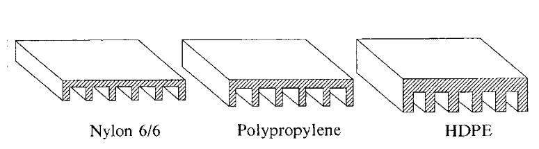
Fig. 3.6
Figure 3.6 shows two-part geometries with identical stiffness values. Sections have exact moduli and moments of inertia values (where any dimension can be chosen) adjusted for material differences.
Though the given example has a straightforward geometry, other geometric features could impact the performance and assembly of a device depending on its material specifications.
At this stage, designers don’t need to select a primary material for product design. However, flexible materials can still be utilized if an unexpected issue arises later in the development process, such as during prototyping and production.
Unfortunately, it appears unlikely that any of these candidates can do the job adequately.
Materials considered for consideration each have their advantages and drawbacks. Designers may have a favorite material based on experience, which can be helpful when working with familiar materials; however, other options may be better suited.
Unfortunately, decisions based solely on the cost of materials or manufacturing often neglect performance or other advantages.
Candidates should be assessed based on their processing costs, end-use performance and overall manufacturing characteristics.
Designers can select the most appropriate materials by carefully considering their properties and characteristics using an almost objective grading system.
Although individual numerical ratings for a house can sometimes be subjective, I believe they are based on actual numerical data.
After considering all factors, a semi-quantitative process will be employed to select the top material candidates based on balance.
Once the initial design and material have been chosen, modifications should be made for manufacturing. The expertise of process engineers and tooling engineers is invaluable here.
Moldability is essential when designing parts. Designers must consider how different stages of the injection molding process affect part geometry.
Every stage of injection molding, from mold filling and packing to cooling and ejection, has its own specific requirements.
Practically, the part should be modified with draft angles to facilitate part ejection and flow (and reduce stress concentrations), radii to improve flow, and surface texture to improve visual appearance due to material shattering of sink marks on the wall side of ribs.
These are just a few potential modifications that could be necessary from a manufacturing perspective.
Once modifications have been made, it’s important to assess their effect on the part’s end-use performance. Design changes such as adding draft angles to ribs can significantly impact maximum deflections or stresses caused by service loading, so be sure to account for this when making modifications.
Figure 3.9 provides a checklist for the part design that can be used during planning or final checks to guarantee all aspects of manufacturing and assembly have been taken into account.
At this stage, a prototype of the final part design is usually created to verify both its manufacturing feasibility and performance.
Prototyping is essential since all the processes (e.g. molding simulations or performance design work) that have been done up until this point are purely theoretical.
Molded plastic parts require special attention, as many manufacturing-related issues such as weld line appearance and strength, warpage, sink marks, etc. cannot be predicted in advance.
Prototyping parts from desired production material is essential in order to get realistic results. This may involve building either a single cavity tool (or unit) for smaller components or soft (usually simplified) tools for larger items.
Prototyping can be expensive and time-consuming. However, it’s more effective to detect manufacturing or end-use performance issues with a single cavity or soft tool than with multiple cavities of hard tooling to avoid the big rework later.
To reduce tool rework expenses, steel safety practices should be adhered to.
low volume injection molding(most of them is below 100 pcs) is invaluable for testing engineering functions and manufacturing processes. But there’s another type of prototyping that’s much faster – rapid prototyping. These models can be created quickly (within hours or even days) and serve as valuable models for communication and limited functionality long before the actual tool is constructed.
After parts and prototype tools have been evaluated and modified, pre-production tools or production tools can be constructed.
It is common to begin the basic work on tools before the deadline in order to save time. After these tools have been constructed and tested, manufacturing can begin.